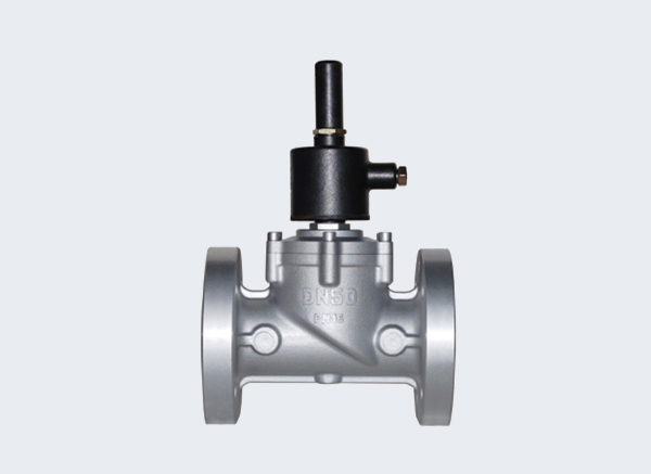
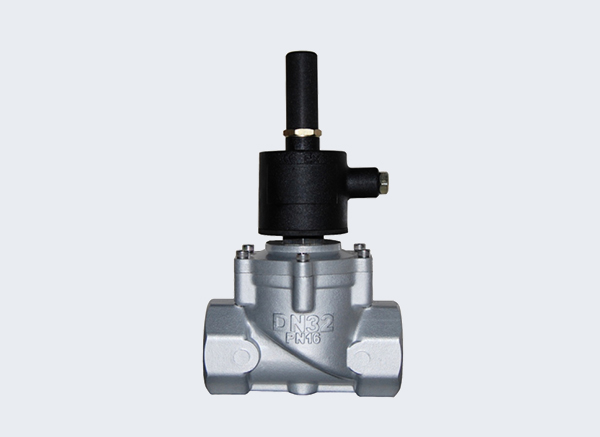
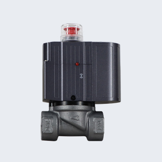
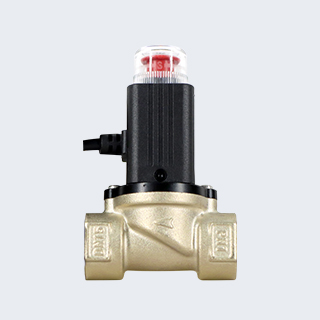
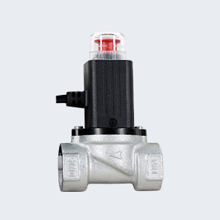
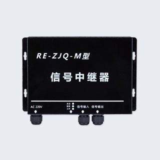
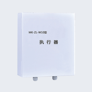
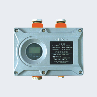
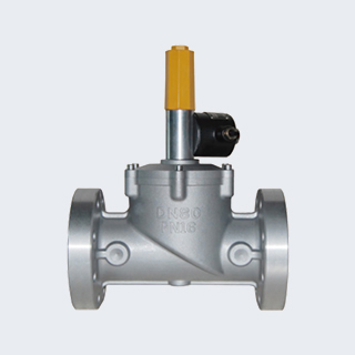
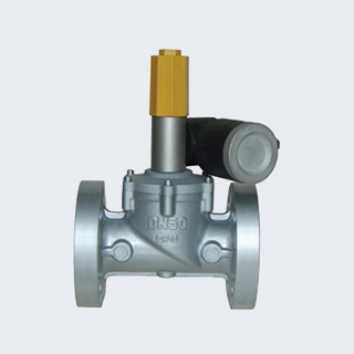
Product Description:
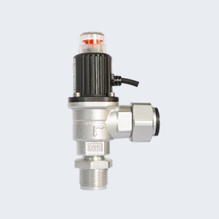
This industrial-grade flameproof solenoid valve features manual reset for valve opening under power, automatic valve closure on power loss, and latching of valve status.
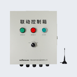
As an emergency safety cut-off device for gas pipelines, the electromagnetic gas emergency shut-off valve can be linked with gas leakage alarm systems, fire alarm systems and other intelligent control terminals. It supports on-site and remote emergency gas cut-off in automatic or manual mode, safeguarding gas pipeline transportation and gas utilization safety.
The valve remains open when energized. Once gas leakage occurs, the alarm will cut off power to the valve for automatic closure. Valve reopening must be performed manually with power supplied. The product complies with relevant safety regulations and gas accident handling standards.
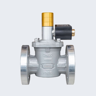
Product Features:
※ Flameproof Design: The explosion-proof cover is made of steel material. It features outdoor waterproof performance, external impact resistance, and strong adaptability to ambient temperature changes.
※ Valve Closing Mode: The valve can be closed by cutting off power to the coil, with an additional manual closing function.
※ Valve Opening Mode: Manual on-site opening is required under powered status, which fully complies with gas accident handling specifications.
※ Position Holding Mode: Adopts a bistable structure, maintaining normally open or normally closed state without any power supply.
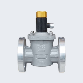
※ Fast Closing Speed: Valve closing time is less than 1 second.
※ Isolated Safety Structure: The internal medium passage is completely isolated from the outside environment, ensuring safe and stable operation.
※ Premium Static Sealing: Adopts a three-point alignment structure consisting of guide pins, manual rods and pistons, achieving tight and reliable sealing performance.
※ Patented Dynamic Sealing Technology: Equipped with a two-stage dynamic sealing structure. The dynamic sealing ring supports automatic wear compensation, effectively extending the service life of the valve.
Product Selection:
| Thread | Nominal Diameter (mm) | Pipe Thread | Dimensions (mm) |
| L | H | H1 | / |
| DN25 | G1" | 100 | 235 | 210 | / |
| DN32 | G11/4" | 150 | 265 | 230 | / |
| DN40 | G11/2" | 150 | 265 | 230 | / |
| DN50 | G2" | 155 | 285 | 245 | / |
Note: In all tables, L = Length; H = Height; H1 = Center Height.
| Thread | Nominal Diameter (mm) | Dimensions (mm) |
| L | H | H1 | ∅D | ∅K | N-∅1 |
| DN25 | 150 | 265 | 210 | 115 | 85 | 4-∅14 |
| DN32 | 215 | 300 | 235 | 135 | 100 | 4-∅18 |
| DN40 | 215 | 305 | 235 | 135 | 110 | 4-∅18 |
| DN50 | 220 | 320 | 245 | 160 | 125 | 4-∅18 |
| DN65 | 280 | 420 | 335 | 180 | 145 | 4-∅18 |
| DN80 | 300 | 450 | 355 | 195 | 160 | 8-∅18 |
| DN100 | 355 | 480 | 375 | 215 | 180 | 8-∅18 |
| DN150 | 480 | 600 | 460 | 280 | 240 | 8-∅23 |
| DN200 | 550 | 810 | 640 | 335 | 295 | 12-∅23 |
Note: In all tables, L = Length; H = Height; H1 = Center Height; ∅D = Flange Outer Diameter; ∅K = Bolt Circle Diameter; N-∅1 = Quantity and Size of Bolt Holes.
Structure Drawing