Product Description:
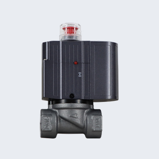
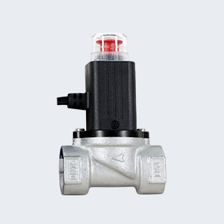
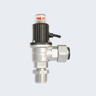
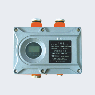
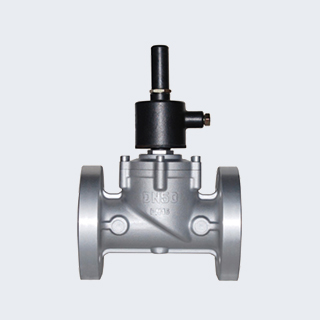
This series is industrial-grade flameproof solenoid valves with latching function. The valve is opened by manual reset under power supply and closed automatically upon power failure.
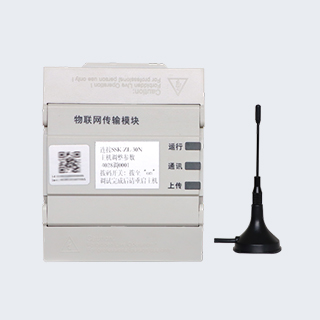
As an emergency safety cut-off device for gas pipelines, the electromagnetic gas emergency shut-off valve can be connected to gas leakage alarm systems, fire protection systems and other intelligent alarm control terminals. It enables on-site and remote emergency gas cut-off via automatic or manual operation, so as to ensure the safety of gas pipeline transmission and gas consumption.
The valve stays open when powered on. In the event of gas leakage, the alarm will cut off power to the solenoid valve, and the valve will close automatically. The valve can only be manually reopened when power is restored, which complies with safety management regulations and gas accident handling requirements.
Product Features:
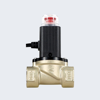
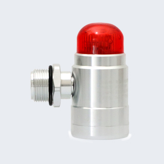
※ Flameproof design: The explosion-proof cover is made of steel. It is outdoor waterproof, impact resistant and capable of withstanding ambient temperature variations.
※ Valve closing mode: Closing by de-energizing the energy storage module or manual operation.
※ Valve opening mode: On-site manual opening under powered condition, in compliance with gas accident handling requirements.
※ Holding mode: Bistable structure, maintaining open or closed state without power supply.
※ Closing speed: Less than 1 second.
※ Structure: The internal medium is fully isolated from the outside for high safety and reliability.
※ Static sealing: Three-point alignment structure (guide pin, manual rod, piston) for reliable tight sealing.
※ Dynamic sealing: Two-stage sealing structure. The dynamic sealing ring adopts automatic wear compensation to prolong service life. Patented technology.
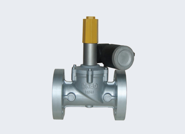
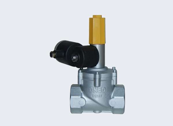
Product Selection:
| Thread | Nominal Diameter (mm) | Pipe Thread | Dimensions (mm) |
| L | H | H1 | / |
| DN25 | G1" | 100 | 235 | 210 | / |
| DN32 | G11/4" | 150 | 265 | 230 | / |
| DN40 | G11/2" | 150 | 265 | 230 | / |
| DN50 | G2" | 155 | 285 | 245 | / |
Note: In all tables, L = Length; H = Height; H1 = Center Height.
| 螺纹 | 公称直径 mm | Dimensions (mm) |
| L | H | H1 | ∅D | ∅K | N-∅1 |
| DN25 | 150 | 265 | 210 | 115 | 85 | 4-∅14 |
| DN32 | 215 | 305 | 240 | 135 | 100 | 4-∅18 |
| DN40 | 215 | 305 | 240 | 135 | 110 | 4-∅18 |
| DN50 | 220 | 325 | 250 | 160 | 125 | 4-∅18 |
| DN65 | 280 | 400 | 315 | 180 | 145 | 4-∅18 |
| DN80 | 300 | 410 | 320 | 195 | 160 | 8-∅18 |
| DN100 | 355 | 460 | 355 | 215 | 180 | 8-∅18 |
| DN125 | 460 | 600 | 480 | 245 | 210 | 8-∅18 |
| DN150 | 480 | 650 | 510 | 280 | 240 | 8-∅23 |
| DN200 | 550 | 850 | 680 | 335 | 295 | 12-∅23 |
Note: In all tables, L = Length; H = Height; H1 = Center Height; ∅D = Flange Outer Diameter; ∅K = Bolt Circle Diameter; N-∅1 = Quantity and Diameter of Bolt Holes.
Structure Drawing: